Contents |
Explanation
In balanced pair operation, the two wires carry equal and opposite signals and the destination detects the difference between the two. This is known as differential mode transmission. Noise sources introduce signals into the wires by coupling of electric or magnetic fields and tend to couple to both wires equally. The noise thus produces a common-mode signal which is cancelled at the receiver when the difference signal is taken.This method starts to fail when the noise source is close to the signal wires; the closer wire will couple with the noise more strongly and the common-mode rejection of the receiver will fail to eliminate it. This problem is especially apparent in telecommunication cables where pairs in the same cable lie next to each other for many miles. One pair can induce crosstalk in another and it is additive along the length of the cable. Twisting the pairs counters this effect as on each half twist the wire nearest to the noise-source is exchanged.
Providing the interfering source remains uniform, or nearly so, over the distance of a single twist, the induced noise will remain common-mode. Differential signaling also reduces electromagnetic radiation from the cable, along with the associated attenuation allowing for greater distance between exchanges.
The twist rate (also called pitch of the twist, usually defined in twists per meter) makes up part of the specification for a given type of cable. Where nearby pairs have equal twist rates, the same conductors of the different pairs may repeatedly lie next to each other, partially undoing the benefits of differential mode. For this reason it is commonly specified that, at least for cables containing small numbers of pairs, the twist rates must differ.[1]
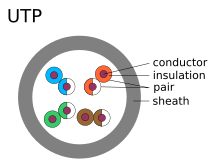
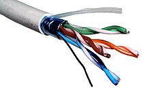
In contrast to FTP (foiled twisted pair) and STP (shielded twisted pair) cabling, UTP (unshielded twisted pair) cable is not surrounded by any shielding. It is the primary wire type for telephone usage and is very common for computer networking, especially as patch cables or temporary network connections due to the high flexibility of the cables.
History
The earliest telephones used telegraph lines, or open-wire single-wire earth return circuits. In the 1880s electric trams were installed in many cities, which induced noise into these circuits. Lawsuits being unavailing, the telephone companies converted to balanced circuits, which had the incidental benefit of reducing attenuation, hence increasing range.As electrical power distribution became more commonplace, this measure proved inadequate. Two wires, strung on either side of cross bars on utility poles, shared the route with electrical power lines. Within a few years, the growing use of electricity again brought an increase of interference, so engineers devised a method called wire transposition, to cancel out the interference.
In wire transposition, the wires exchange position once every several poles. In this way, the two wires would receive similar EMI from power lines. This represented an early implementation of twisting, with a twist rate of about four twists per kilometre, or six per mile. Such open-wire balanced lines with periodic transpositions still survive today in some rural areas.
Twisted pair cables were invented by Alexander Graham Bell in 1881.[2] By 1900, the entire American telephone line network was either twisted pair or open wire with transposition to guard against interference. Today, most of the millions of kilometres of twisted pairs in the world are outdoor landlines, owned by telephone companies, used for voice service, and only handled or even seen by telephone workers.
Unshielded twisted pair (UTP)
UTP cables are found in many Ethernet networks and telephone systems. For indoor telephone applications, UTP is often grouped into sets of 25 pairs according to a standard 25-pair color code originally developed by AT&T. A typical subset of these colors (white/blue, blue/white, white/orange, orange/white) shows up in most UTP cables.For urban outdoor telephone cables containing hundreds or thousands of pairs, the cable is divided into smaller but identical bundles. Each bundle consists of twisted pairs that have different twist rates. The bundles are in turn twisted together to make up the cable. Pairs having the same twist rate within the cable can still experience some degree of crosstalk. Wire pairs are selected carefully to minimize crosstalk within a large cable.
UTP cable is also the most common cable used in computer networking. Modern Ethernet, the most common data networking standard, utilizes UTP cables. Twisted pair cabling is often used in data networks for short and medium length connections because of its relatively lower costs compared to optical fiber and coaxial cable.
UTP is also finding increasing use in video applications, primarily in security cameras. Many cameras include a UTP output with screw terminals; UTP cable bandwidth has improved to match the baseband of television signals.
While the video recorder most likely still has unbalanced BNC connectors for standard coaxial cable, a balun is used to convert from 100-ohm balanced UTP to 75-ohm unbalanced. A balun can also be used at the camera end for ones without a UTP output. Only one pair is necessary for each video signal.
Cable shielding
|
|
This article may require cleanup to meet Wikipedia's quality standards. No cleanup reason specified. Please add a |reason= parameter to this template. Please help improve this article if you can. The talk page may contain suggestions. (January 2011) |
Main article: Electromagnetic shielding
Twisted pair cables are often shielded in an attempt to prevent
electromagnetic interference. Because the shielding is made of metal, it
may also serve as a ground. However, usually a shielded or a screened
twisted pair cable has a special grounding wire added called a drain
wire.This shielding can be applied to individual pairs, or to the collection of pairs. When shielding is applied to the collection of pairs, this is referred to as screening. The shielding must be grounded for the shielding to work, and is improved by grounding the drain wire along with the shield.
- Shielded twisted pair (STP or STP-A)
- 150 ohm STP shielded twisted pair cable defined by the IBM Cabling System specifications and used with token ring or FDDI networks. This type of shielding protects cable from external EMI from entering or exiting the cable and also protects neighboring pairs from crosstalk.
- Screened twisted pair (ScTP or F/TP)
- ScTP cabling offers an overall sheath shield across all of the pairs within the 100 Ohm[3] twisted pair cable. F/TP uses foil shielding instead of a braided screen. This type of shielding protects EMI from entering or exiting the cable.
- Screened shielded twisted pair (S/STP or S/FTP)
- S/STP (Screened Shielded Twisted Pair) or S/FTP (Screened Foiled Twisted Pair) cabling offer shielding between the pair sets and an overall sheath shield within the 100 Ohm twisted pair cable. This type of shielding protects EMI from entering or exiting the cable and also protects neighboring pairs from crosstalk.
Note that different vendors and authors use different terminology (i.e. STP has been used to denote both STP-A, S/STP, and S/UTP).[3] See below for the ISO/IEC attempt to internationally standardise the various designations.
Comparison of some old and new abbreviations, according to ISO/IEC 11801:
| Old name | New name | cable screening | pair shielding |
|---|---|---|---|
| UTP | U/UTP | none | none |
| STP | U/FTP | none | foil |
| FTP | F/UTP | foil | none |
| S-STP | S/FTP | braiding | foil |
| S-FTP | SF/UTP | foil, braiding | none |
- TP = twisted pair
- U = unshielded
- F = foil shielding
- S = braided shielding
Most common twisted-pair cables
| Name | Type | Bandwidth | Applications | Notes |
| Level 1 | 0.4 MHz | Telephone and modem lines | Not described in EIA/TIA recommmendations. Unsuitable for modern systems.[5] | |
| Level 2 | 4 MHz | Older terminal systems, e.g. IBM 3270 | Not described in EIA/TIA recommmendations. Unsuitable for modern systems.[5] | |
| Cat3 | UTP[6] | 16 MHz[6] | 10BASE-T and 100BASE-T4 Ethernet[6] | Described in EIA/TIA-568. Unsuitable for speeds above 16 Mbit/s. Now mainly for telephone cables[6] |
| Cat4 | UTP[6] | 20 MHz[6] | 16 Mbit/s[6] Token Ring | Not commonly used[6] |
| Cat5 | UTP[6] | 100 MHz[6] | 100BASE-TX & 1000BASE-T Ethernet[6] | Common in most current LANs[6] |
| Cat5e | UTP[6] | 100 MHz[6] | 100BASE-TX & 1000BASE-T Ethernet[6] | Enhanced Cat5. Same construction as Cat5, but with better testing standards. |
| Cat6 | UTP[6] | 250 MHz[6] | 10GBASE-T Ethernet | Most commonly installed cable in Finland according to the 2002 standard. SFS-EN 50173-1 |
| Cat6a | 500 MHz | 10GBASE-T Ethernet | ISO/IEC 11801:2002 Amendment 2. | |
| Class F | S/FTP[6] | 600 MHz[6] | Telephone, CCTV, 1000BASE-TX in the same cable. 10GBASE-T Ethernet. | Four pairs, S/FTP (shielded pairs, braid-screened cable). Development complete - ISO/IEC 11801 2nd Ed. |
| Class Fa | 1000 MHz | Telephone, CATV, 1000BASE-TX in the same cable. 10GBASE-T Ethernet. | Four pairs, S/FTP (shielded pairs, braid-screened cable). Development complete - ISO/IEC 11801 2nd Ed. Am. 2. |


Tidak ada komentar:
Posting Komentar